The objective of the program is to generate a 10MHz square wave at P0.3 on an LPC2119 board. Our lecturer Bryan helped me to check the code but everything seems to be correct except for the result.
Here’s the c code:
[c]
#include
int main (void)
{
IODIR0=0x0200008; //Make P0.3 and P0.21 to be output port
IOCLR0=0x1<<21; //Lit the LED on P0.21
PINSEL0=0x80; //Choosing P0.3 to be Timer0 Match0
T0TCR=2; //Reset the timer0
T0PR=0; //Set pre-scaler to 1
T0MR0=1; //Set match0 to 1
T0EMR=0x30; //Toggle pin when match
T0MCR=0x3; //Reset timer0 when match
T0TCR=1; //Start timer0
while(1) //Endless loop
{}
}
[/c]
As a result, the LED was on but there's no wave coming from P0.3. Bryan told me that in terms of getting full mark in the test, this program will just work because nothing's wrong. However, another group of student managed to generate the wave using timer1. So it must be that we've missed something very silly
Digital system lab session, struggled to make the program to run correctly

-
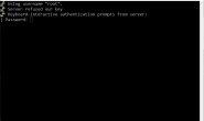
连接SSH时key被服务器拒绝 | SSH server refused our key -
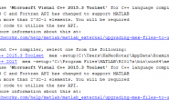
MatConvNet with Visual Studio 2015.3 Toolset and MATLAB R2017a -
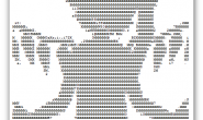
Bad Apple ASCII Javasrcipt字符画版| Bad Apple ASCII Javascript -

PMangar再启动计划 | Revival of PMangar
- 连接SSH时key被服务器拒绝 | SSH server refused our key
- MatConvNet with Visual Studio 2015.3 Toolset and MATLAB R2017a
- Bad Apple ASCII Javasrcipt字符画版| Bad Apple ASCII Javascript
- PMangar再启动计划 | Revival of PMangar
- 这学期要忙起来了| Getting busy this semester
- Python 笔记01| Notes about Python 01
- 学校图书馆真吵| University library is really noisy
- 雅思啊| IELTS…